Part Two: Number 7 is On Track
| Written by | |
|---|---|
| Published | 10/20/2015 |
Part Two: Number 7 is On Track
| Written by | |
|---|---|
| Published | 10/20/2015 |
One of the key issues for the decision to begin the work on Number 7 was the availability of the skill sets and facilities required to accomplish a high quality restoration. This was a major undertaking and as one of the most respected transportation museums in the world it is necessary to only do things that you can do very well. Fortunately, The Henry Ford had a group in place (Railroad Operations) that was responsible to maintain two operating steam locomotives, rolling stock, tracks and signal system to provide historic railroad transportation on a daily basis.
The facility where the Railroad Operations personnel performed this maintenance was the Greenfield Village’s Detroit, Toledo and Milwaukee Roundhouse. Built in 2000 to closely replicate the 1880s DT&M facility in Marshall, Michigan; it was well equipped and had the necessary tools and machines to maintain the Village’s railroad operations.
The expertise to maintain this railroad goes well beyond the service and replacement aspects of a shop. Since there is no steam locomotive “AutoZone”; if something has to be replaced you make it. This requires extensive machining and fabrication capability. Additionally, since replacement of castings or other items sometimes requires detailed relationships with outside suppliers, extensive design and drafting skills were often required.
The physical aspects of Number 7’s restoration began in 2007 with the disassembly process. Disassembly of a locomotive is a time consuming and physically demanding process. Before the major assemblies could be removed many tubes, valves and ancillary systems had to be removed. The fact that these parts had not been touched for over 80 years made this especially challenging.
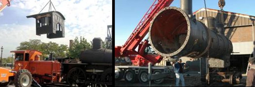
In September of 2007 the removal of the major components began with the separation of the cab (pictured below) from the chassis. In early December the boiler was removed so it could be worked on with unobstructed access to the areas that would need to be replaced (pictured below).
Early in 2008 the process of removing the sections of the boiler and firebox was started along with the removal of hardened scale from the boiler walls. Work on the boiler proceeding through the year removing the sections that would be replaced and preparing the surfaces for installation of the new ones.
After the preparation phase, fabrication of the new sections of the boiler began. One of the most complicated and demanding sections was the rear tube sheet. This is the part that faces the firebox and holds the heat tubes in place so that the heat generated in the firebox can be drawn through the boiler to heat the water and develop steam.
The first phase of the tube sheet forming began with the use of McCabe flanging tool. This pneumatically powered machine, built in 1921, was a common tool in roundhouses of that period. This machine has the capability of forming flanges on sheet steel up to ¾ of an inch thick. The flanging tool would save a significant amount of work but was limited as it could not flange the tight radius needed for the top corners. Forming those portions of the tube sheet would require hand forming.
To facilitate the hand forming an approximately 1.5 inch thick metal die had to be fabricated. This was done by an outside company to Train Operations developed drawings. The partially formed steel sheet was then rigidly attached to the die and the remaining forming was done after the immediate area being formed was heated to red hot by acetylene torches. The heated portion could then be formed by the use of special hammers. These hammers were made of reinforced hard wood that would not put dent marks in the metal when it struck the red hot steel. Dent marks would structurally weaken the metal. The upper corners of the sheet had be cut at the centerline of the curve so that, when formed, there would be a smooth joint that could be welded with integrity.
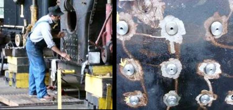
After the forming process was completed the sheet would have to be drilled to accept the heat tubes and stay bolts. Since the heat tubes were almost 12 ft. long and required a very close fit at each end to assure sealing; locating and drilling the holes had to be accomplished with complete accuracy.
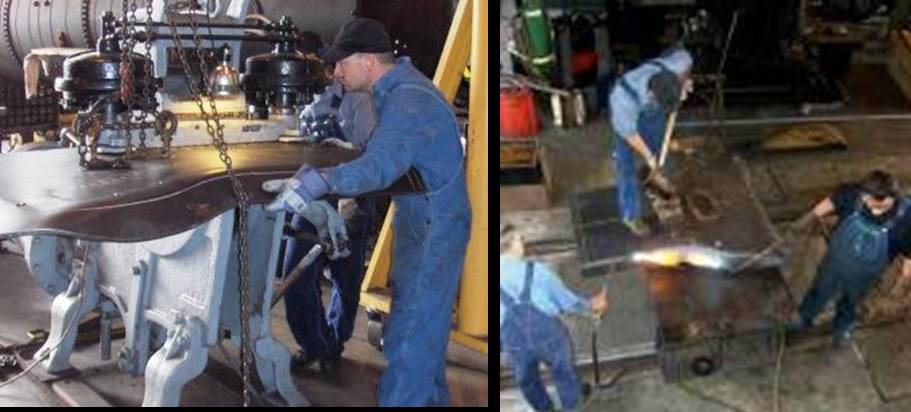
Work on the boiler continued through the end of 2008 and into 2009 with fabrication of the firebox floor and door sheet. Throughout all of this fabrication the parts had to be very precise to provide accurate fitment. Repairs like these are critical to the safety of a trains operation. Boilers are very closely regulated by the government and all welding has to be done by a boiler certified welder. These welders will not compromise on flushness and alignment of the components to assure high quality welds.
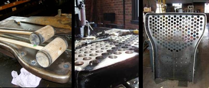
This picture shows the thickness of the metal sheet that had to be formed by hand. Right (photo by Shirley Damps), The formed and drilled tube sheet is ready to be welded to the back of the boiler. The larger (upper) holes are for the heat tubes and the lower holes are for the stay bolts.
The welded elements of the boiler are only part of the story. The non-cylindrical parts like the firebox and crown sheet have to be held in position inside the boiler by a device called a stay bolt. Stay bolts are threaded rods that hold the firebox and crown sheet into position while still allowing the water to circulate around it. New stay bolts would have to be sized and machined for each individual location by the roundhouse crew.
Once the stay bolts are installed (above) the exposed ends are “upset” like a rivet so they are sealed and fixed into position. When the stay bolt is fabricated it is drilled down its center (above)so that if it cracks or breaks during service, a small trail of water or rust will appear on the head indicating an internal failure of the stay bolt.
A locomotive boiler like the one in Number 7 has hundreds of these bolts that have to be individually machined to assure proper fit and sealing. Many of these would have to be replaced due to the new sections of the boiler.
this photo shows the threaded stay bolts in place. Once installed the heads are “upset” like rivets.
Once the components of the boiler were installed it was painted with high temperature epoxy paint and the insulation blocks began to be installed. The “calcium silicate” insulator blocks (above) replaced the asbestos removed in 1997 and was necessary to help keep heat in the boiler and provide an insulated barrier to protect the “jacketing.” The “jacketing” was decorative but primarily served to keep the insulation blocks in place, heat inside the boiler and protect train personnel.
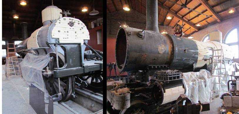
this later photo shows the installation of the first piece of jacketing (center) over the insulation.
Parallel to the work on the boiler was the restoration of the tender. To ensure that Number 7 would have a tender that would hold up to daily use it was decided that a new frame would be required. Additionally, the original frames wooden construction would be replaced by a stronger all steel frame assembly, an option on the original factory builds.
The upper part of the tender was sand blasted to bare metal and the 3,350 gallon water tank was tested to assure integrity. After the sandblasting was complete, it was painted the “as delivered” green with the name Detroit & Lima Northern hand painted on the side along with the painted trim indicated by the Baldwin photos.
Although the Baldwin “as built” information identified a specific color name there were no color chips to tell exactly what that name actually looked like. The color established was the result of significant research and the color mix selected came from Chris Dewitt of the Nevada State Railroad Museum. A 1913 Baldwin in their collection had a small section that provided the only known “color chip” of the original paint. This sample was analyzed and they provided a chip from that analysis for our restoration. For the railroad purists it is important to note that each Baldwin painter mixed his own paint; it is unlikely that anyone could point to a replicated color and say “this was an exact match.”
Left, work on the tender had progressed throughout 2011. This January 2012 photo shows the tender upper section after being sandblasted, primed and finished painted. Right, the February 2012 photo shows the start of construction on the new Tender frame. The steel beams replace the original wooden frame.
The tender restoration was completed later in the year and the work on Number 7 locomotive started to show real progress.
Don LaCombe is former Supervisor of the Transportation and Crafts Program at The Henry Ford.Additional Readings:
Keywords | |
|---|---|
Themes |